Regenerative Thermal Oxidizers
Thermal oxidizers have been used for air pollution control for many decades and are one of the most accepted technologies for the destruction of volatile organic compounds (VOCs), hazardous air pollutants (HAPs), and to some degree, odor. These pollutants are generally organic and can be destroyed by oxidation at a high temperature, i.e., converted into CO2 and H2O before being released into the atmosphere.
Thermal oxidizers are sometimes referred to as thermal incinerators. The technology can be compared to a “burner in a box”. They come in many different sizes, shapes, and configurations but all operate on the same basic principle of thermal combustion/oxidation. There are several types of thermal oxidizers that you may hear of in the marketplace but most often there are two types; direct fired thermal oxidizers (DFOs) and regenerative thermal oxidizers (RTOs).
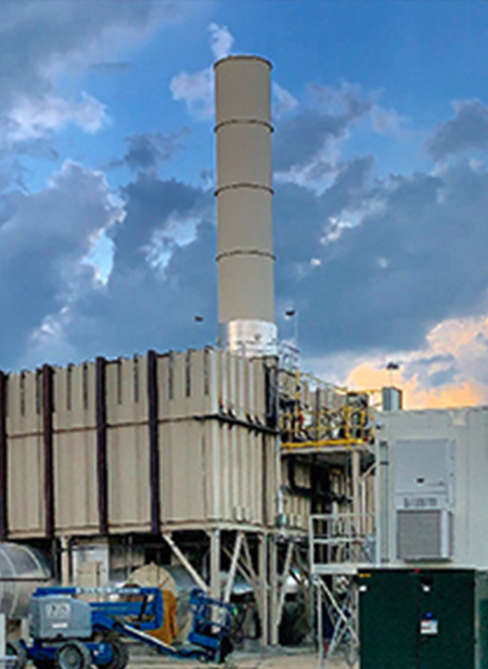
You may also be familiar with catalytic oxidizers, either as regenerative catalytic oxidizers (RCOs) or recuperative catalytic oxidizers. A catalytic oxidizer is simply a thermal oxidizer with an added catalyst that allows effective oxidation at a much lower temperature.
RTO Destruction Efficiency of 95-99% Thermal Efficiencies +97%
Most Efficient Technology for VOC Abatement
The main purpose of an RTO is the destruction of VOCs and HAPs, commonly referred to as its Destruction Removal Efficiency (DRE). DRE is the percentage of VOCs/HAPs that are destroyed by the RTO. The DRE is determined by comparing the inlet concentration of VOCs/HAPs to the outlet concentration, typically in parts-per-million (ppm). Most RTOs are designed to achieve 95%-99% DRE.
RTOs are the most common and most widely used type of oxidizer today. It is the preferred oxidizer technology designed to destroy VOCs, HAPs, and other airborne pollutants. RTOs are the preferred choice due to their high destruction efficiencies and their ability to recover most of the thermal heat that is generated for the destruction of VOCs and HAPs.
The basic design parameters for any RTO in use today are based on the three “T’s”: Temperature, Time, and Turbulence. These three T’s are the basis of the RTO combustion chamber whereby the
- Temperature is elevated high enough to ignite the incoming VOCs/HAPs
- Time refers to the duration the VOCs/HAPs remain in the RTO combustion chamber
- Turbulence refers to the mixing of the combustion chamber temperature with the incoming process air
The three “T’s” combined, ensure that all of the VOCs/HAPs are destroyed before exiting the exhaust stack.
How Does an RTO Work?
Basics
The operation of a Regenerative Thermal Oxidizer (RTO) is based upon a chemical/thermal process and a mechanical process. The chemical/thermal process is the application of heat to a process exhaust stream that contains organic Volatile Organic Compounds (VOCs) and Hazardous Air Pollutants (HAPs). This application of heat oxidizes these pollutants from their initial chemical state to two inert compounds: CO2 and H2O.
Examples of Typical Organic Compounds
- Acetal C6H14O2
- Acetone C3H6O
- Benzene C6H6
- Butanol C4H10O
- Cyclohexanol C6H12O
- Formaldehyde CH2O
- Heptane C7H16
- Isopentane C5H12
Examples of Conversion of VOC’s to Inert Compounds
- Formaldehyde CH2O + O2 > CO2 + H2O
- Heptane C7H16 + 11O2 > 7CO2 + 8H2O
- Hexane 2C6H14 + 19O2 > 12CO2 + 14H2O
The RTO Mechanical Process
The RTO mechanical process operates on the principle of alternating gas flow through multiple “beds” of ceramic heat exchange media. The inlet gas is first drawn into the system and up through the inlet bed where the gas pre-heats by contact with ceramic heat media. As the gas moves up through the ceramic media, the gas reaches temperatures of 1,400°F to 1,475°F. The gas then enters the combustion chamber where a burner (typically natural gas fired) operates to increase the gas temperature to between 1,500°F to 1,750°F. Thus, the previous reference to an RTO as a “burner in a box”.
Combustion Chamber Set Point
This temperature is referred to as “combustion chamber set point” and is the point where nearly all VOC and HAP compounds are destroyed and converted to CO2 and H2O. At this point the process gas, now cleaned of contaminants and heated, is directed downward through the outlet heat exchange media bed. The gas at the combustion chamber temperature relinquishes its heat to the ceramic media as it travels downward through the outlet bed.
After a two- to three-minute period, the RTO cycles so that valves reverse the airflow through the system (see below). This back and forth process, or cycle, is referred to as a regenerative thermal process.
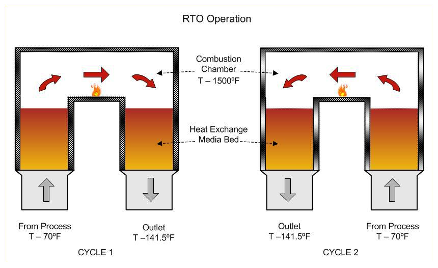
RTO Operations
Thermal Energy Recovery (TER)
The continual cycling of the RTO beds and subsequent recovery of heat from the ceramic media described above is referred to as Thermal Energy Recovery (TER) and is one of the key aspects of the RTO system. This regenerative process allows for a very high percentage of heat recovery and is rated based upon the percent of heat recovered. Typical TER values of the RTO will be in the 95-97% range.
The result is a clean air composed of CO2 and H2O that is approximately 50-100°F hotter than the incoming air and is then routed through exhaust stack into the atmosphere.
GEOENERGY® GEOTHERM® Regenerative Thermal Oxidizer
The Geoenergy® GeoTherm® RTO is a regenerative thermal oxidizer (RTO) that destroys volatile organic compounds (VOCs), hazardous air pollutants (HAPs) and odors from a variety of industrial process streams, while minimizing energy use and cost.
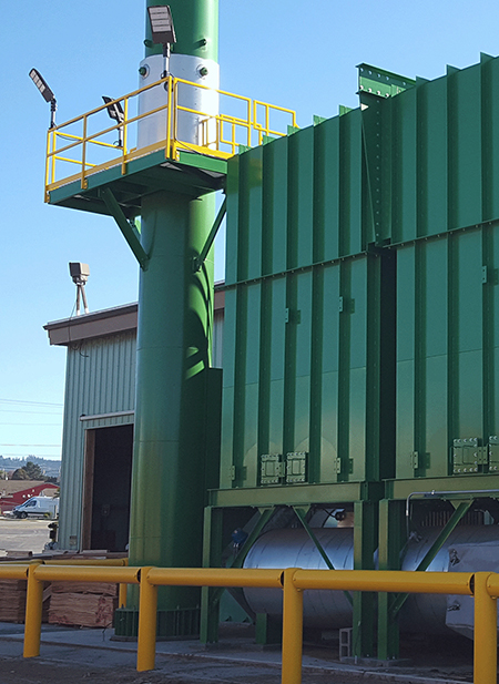
Thermal Oxidizer with environmental compliance
What’s Different About the GEOENERGY® GEOTHERM® RTO?
It’s the proven optimized technology supported by the expertise and experience of the LDX Solutions team, as well as the team’s and technology’s historical track record in ensuring long-term environmental compliance.
Our 35+ years of installing GeoTherm® RTO and GeoCat® RCO systems in North America demonstrates our commitment to our customers and to the reliability of our designs. Our installation list demonstrates our ability to meet a wide range of industry needs and ensures that our customers’ needs to optimize energy consumption with a robust, reliable system will be met. Along with our continued efforts of our aftermarket technical team to support installations long after start-up and commissioning have occurred, these advantages go beyond the offering of a cost-effective system.
GEOTHERM® RTO Features
Simplicity Meets Performance
The GeoTherm® RTO uses a simple, state-of-the-art design to achieve the highest thermal and destruction efficiencies. The intent of an RTO is to decompose volatile organic compounds (VOCs), hazardous air pollutants (HAPs) into innocuous CO2 and H2O by heating the exhaust air to a very high temperature.
The GeoTherm® RTO design is available in multi-canister arrangements for airflows ranging from 2,500 scfm to over 200,000 scfm. Either forced draft or induced draft fan arrangements are utilized depending on the upstream application. The GeoTherm® RTO design utilizes fast acting poppet valves and can include any arrangement/combination of ceramic heat exchange media (structured, or random type). The LDX Solutions engineers select the arrangement of ceramic heat exchange media specifically for the application in order to optimize operating costs and VOC destruction efficiency. This means up to 99% VOC destruction and 97% thermal efficiencies for environmental compliance, year in and year out. In applications with higher VOC loadings the system may even be able to operate in a self-sustaining mode in which no additional fuel is necessary to destroy VOCs.
Fast-Acting Poppet Valves
The GeoTherm® RTO system is a legacy RTO utilizing multiple, fast acting poppet-style diverter valves located at ground level to control the direction of flow through the RTO unit. These valves act together to direct the gas stream into and out of heat recovery chambers located directly above each valve.
Each heat recovery chamber is a vertical section filled with ceramic media. Working in tandem, the diverter valves alternate the direction of flow through the unit on a pre-determined cycle. This back-and-forth, regenerative operation allows the GeoTherm® RTO to recover 95% of the heat generated in the burner chamber and greatly minimizes fuel costs.
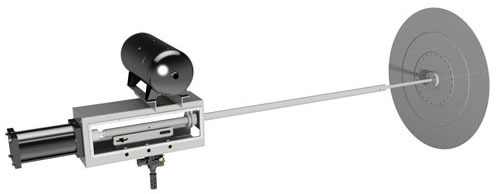
Geoenergy Single-Blade, Dual-Seat Poppet Valve
Features
Resistance to Solids Accumulation
With the valve disk and valve seat located approximately eight (8) inches above the floor of the housing, the unlikely occurrence of heavy deposits of solids does not interfere with the function of the valve.
Resistance to Organic Buildup
This feature is particularly important for gas streams containing condensable organics. Because the valve disk is heated by the outlet gas stream during each cycle, the valve is always hotter than the temperature of the inlet gas stream. This prevents condensation of organic compounds that buildup on the valves and seats.
Resistance to Deformation of Valve or Seat
Since the valve disk seats in both directions, (on both the inlet and outlet seats, ) the disk will not take a permanent set from seating in only one (1) direction.
Industries Served
Geoenergy® Brand
Our RTOs have been operating successfully for over 26+ years in some of the harshest process environments in the air pollution control industry, serving the industries of:
- Automotive
- Carbon Fiber
- Chemical Processing
- Engineered Wood Products
- Ethanol
- Fiber Manufacturing
- Fiberglass/Mineral Wood Insulation
- Flooring
- Foundry
- Insulation Manufacturing
- Oil & Gas
- Packaging & Printing
- Printing & Flexography
- Petrochemical
- Pharmaceutical
- Pulp & Paper
- Rendering
- Semiconductor
- Styrene
- Surface Finishing/Coating
- Tire Manufacturing
- Wastewater Treatment
- Wood Products
GEOTHERM® RTO Systems Benefits
- 95 to 97% thermal efficiency (TER)
- Up to 99% destruction efficiency (DRE)
- Customized Ceramic Media Bed Configuration – plugging / chemical corrosion resistant
- Simple, fast-acting poppet valve design
- Resists condensation of organics on the poppet valve – valve remains hotter than the inlet gas stream, remaining free of buildup
- Minimal moving parts per Heat Recovery Chamber (HRC) – Only one (1) poppet valve per HRC, i.e., only two (2) valves per RTO
The All-New EVOlution RTO®
The next Evolution in RTO design & performance, the EVOlution RTO®. LDX Solutions has developed a state-of-the-art RTO that combines the highest performance and reliability in the marketplace today. No need to compromise – The New Standard is Here.
- Based on 35+ Years of RTO Experience
- Incorporates Superior Refinements Based on Years of Customer Input
- Minimum Moving Parts – Less Maintenance
- No Compressed Air Requirements
- State-of-the-Art Controls and User Interfaces
- Prewired and Factory Assembled
- Simple, Quick Installation
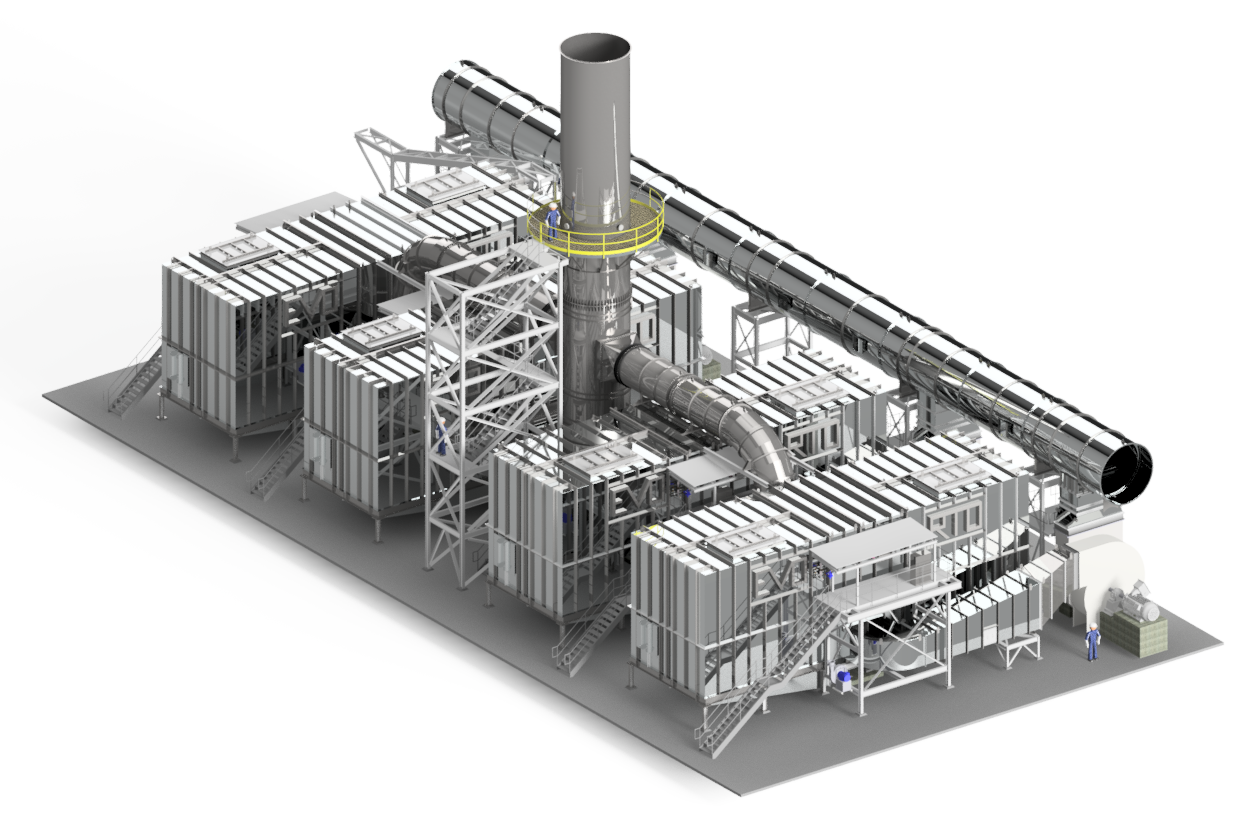
EVO RTO
The Story
The EVOlution RTO® is the product of over 35 years of LDX team experience with regenerative thermal oxidation technology. Engineered and tested based on input from RTO users, its design addresses historical shortcomings and incorporates “what works well”. EVOlution RTO® achieves over 99% destruction efficiency (DRE) and up to 97% thermal energy recovery (TER). Designed for maximum shop assembly resulting in higher quality construction and lower installation cost, EVO features innovations that deliver quiet, reliable operation with virtually no impact on the upstream process. Our dedicated and results oriented team will ensure your RTO will efficiently operate resulting in lower utility costs.
The What
At LDX Solutions, our experts are addressing our customer’s needs by including these features:
- Low noise operation
- Low fuel consumption
- High uptime with minimal process interruption
- Simple plug and play operation
- Easy-to-use graphical interface
- Low electrical consumption
- No compressed air required
- Minimized NOx and CO emissions
The How
The EVOlution RTO® is designed with these technological advantages:
- Low-profile design
- High destruction efficiency across a wide range of solvent concentrations
- Ability to treat a wide range of VOCs, HAPs, solvents, and organic compounds
- Shop assembly and testing
- Fast installation – 1 – 2 weeks
Benefits of the EVOlution RTO®
Evolution RTO™ owners benefit from the best RTO features currently available – The New Standard. The pre-engineered design combined with the reassurance of industry experts provides an unparalleled customer experience.
- +99% VOC and HAP destruction efficiency (DRE)
- Thermal efficiency as high as 97% (TER)
- Flow range from 5,000 to 120,000 SCFM
- Minimal pressure fluctuations
- Increased residence time for lower CO and NOx emissions
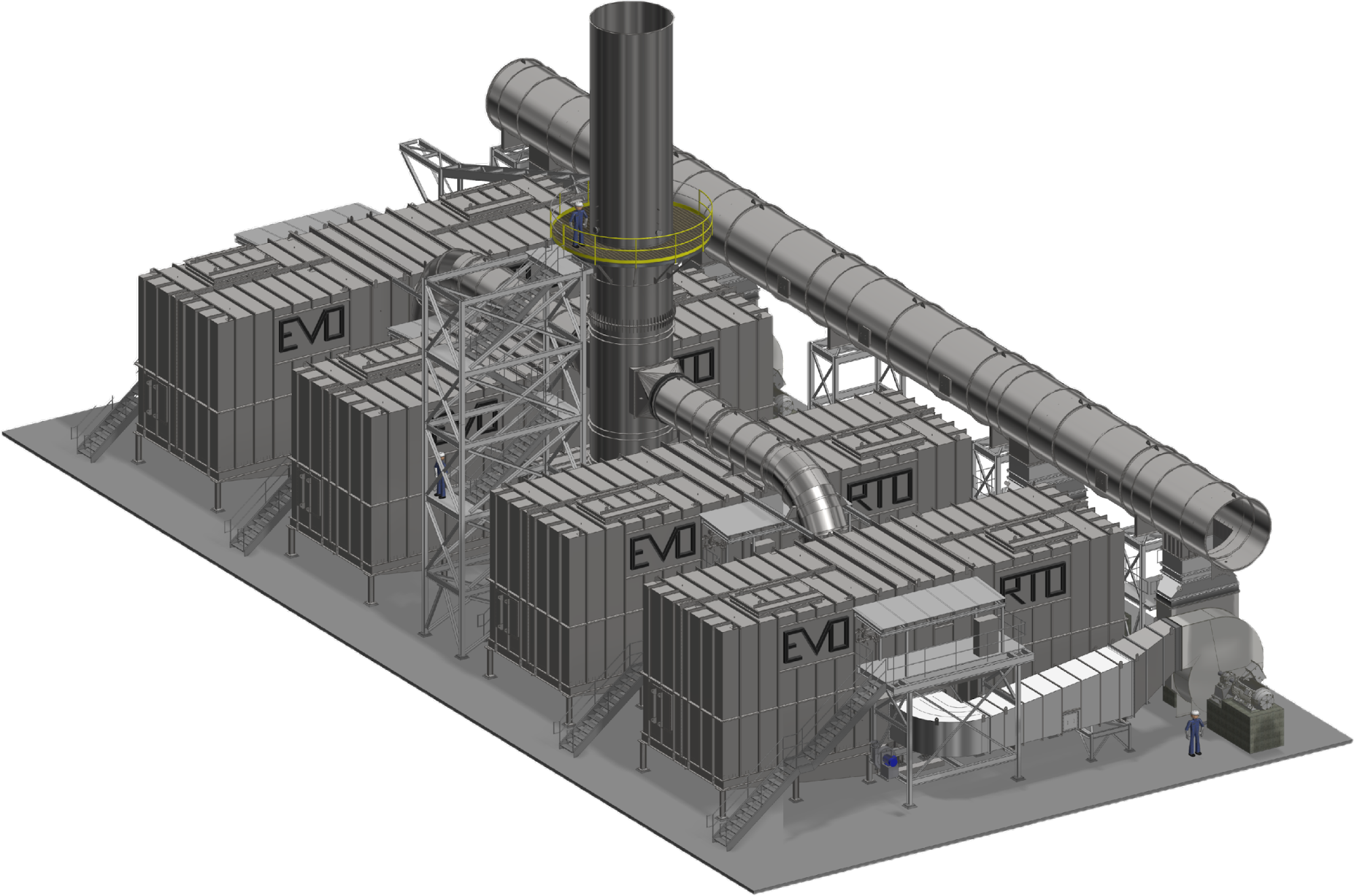
Illustration of EVO RTO
Learn More About the Benefits of EVOlution RTO®
For A Cleaner World
The EVOlution RTO® selection process is simple. An LDX Solutions representative will work alongside you to select the system that meets your needs for today and the future.
Get started by contacting us today!
