
by Steven A. Jaasund, PE | LDX Solutions, Inc.
The cement and lime industries are experiencing an increased environmental concern about carbon dioxide emissions. This will likely drive the installation of CO2 scrubbers at kilns in both sectors. Recent experience with CO2 scrubbers in other industries has demonstrated the importance of the cleanliness of the gases entering a scrubber system. In particular, solid and liquid particles such as sulfuric acid mist will cause problems such as excessive reagent consumption and equipment fouling. This paper will describe the potential of wet electrostatic precipitators to significantly reduce the particulate load at the inlet to a CO2 scrubber to minimize reagent consumption and maintenance problems at the downstream scrubber.
Introduction
There is a rapidly growing interest in technologies to abate CO2 emissions worldwide. Reductions in current rates of carbon dioxide emissions from existing sources are becoming a pillar of the world’s strategy to reduce the greenhouse gas concentration in the atmosphere. This strategy is particularly relevant to the cement industry because of the nature of the process, which involves both the combustion of fossil fuels and the conversion of calcium carbonate to calcium oxide by separating the CO2 molecule.
Much of the attention directed towards CO2 emission abatement is focused on CO2 scrubbing technologies. Such technologies are well developed. Most use amines to absorb CO2 and then regenerate the amine solution to yield a concentrated stream of nearly pure CO2 gas which can then be reused or permanently sequestered. Such CO2 scrubbing systems work best when the incoming gases are free of undesirable impurities. Thus, cleaning the incoming gases is essential to the overall CO2 emission control process. This paper will address the use of wet electrostatic precipitation systems to affect this inlet gas cleaning step.
Industry background
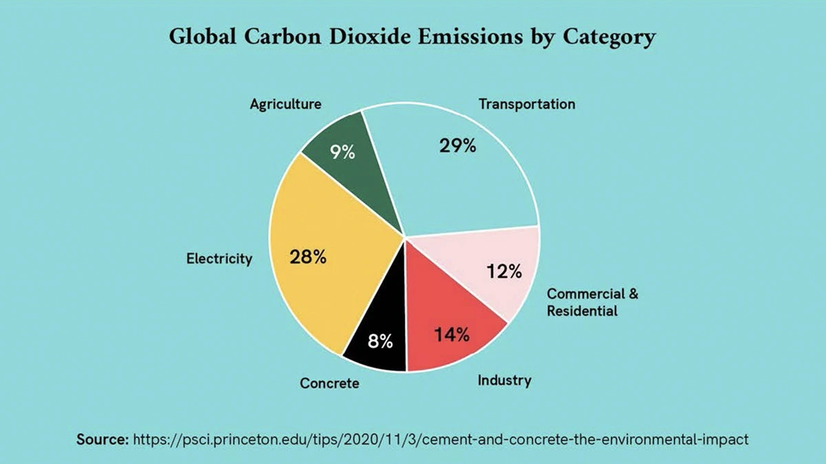
The cement and lime industries are responsible for about 8% of global CO2 emissions. In 2021, these industries emitted an estimated 2.9 billion tons of CO2. This is more than the CO2 emissions from aviation or the entire European Union. The primary source of CO2 emissions from the cement industry is the production of clinker which is the main ingredient in cement; for the lime industry is the calcination of limestone. When limestone is heated to high temperatures, it decomposes and releases CO2. The other primary source of CO2 emissions from the cement and lime industries is the combustion of fuels to heat the kilns. This accounts for about one-third of the total emissions. There are 99 cement plants in the US. There are 96 operating kilns in the lime industry, with another 177 lime kilns in the pulp and paper industry. Given these facts, it is no surprise that the cement and lime industries are the second largest CO2-emitting industry behind electric power generation. Clearly, the industry faces a significant challenge.
CO2 scrubbers
The most widely applied CO2 scrubbing technology uses an aqueousmonoethanolamine (MEA) solution to absorb dilute CO2 and render it into a concentrated form after desorption. The concentrated CO2 stream is then suitable for sequestration, enhanced oil recovery, or other industrial uses. There are many full-scale CO2 scrubbers of this type in operation, and they have been shown to effectively reduce CO2 emissions from flue gases by more than 90%. While there are also several other processes in various stages of development, the MEA scrubbing process appears to be the most widely accepted. There is little question that this technology is mature and proven effective.
However, while the MEA CO2 scrubbing process is proven, it is also costly to operate. There is much work proceeding that is directed at minimizing OPEX for these scrubbers. Still, even under the best conditions, an MEA scrubbing system could consume up to 30% of the power of an upstream coal-fired generating station. One of the main OPEX factors is solvent loss, and a contributing factor to solvent loss is the presence of contaminants in the inlet gas stream. Reported experience also shows that the cleanliness of the inlet gas stream is essential in minimizing maintenance costs. Solid particulate matter in the incoming gas stream can foul equipment such as heat exchangers in the scrubbing system.
These contaminants can be solid and/or liquid particles that form when the inlet gas stream is cooled by saturation before contact with the CO2 absorbing solution. Of particular concern is the sulfuric acid mist that forms in this way.
Wet Electrostatic Precipitators
The CO2 scrubbing process must start with the gas stream in a saturated, wet state. That step may have been accomplished in an existing SO2 scrubber in applications such as coal-fired boilers. In other applications where fabric filters or dry electrostatic precipitators are employed, a wet quench system would be required before the gas stream could enter the CO2 scrubber. Regardless, such upstream quench cooling will be necessary. After this quench step, wet electrostatic precipitators (wet ESP) would fit.
Wet ESPs have several characteristics that make them well-suited for pre-cleaning a gas stream prior to treatment in a CO2 scrubber. First, because they operate in cooled, saturated conditions, they can capture condensables such as acid mist and heavy organics. Additionally, wet ESPs are not sensitive to the chemical makeup of the collected particles, such as dust resistivity, a factor that is very important in dry ESP systems.
Because of these and other factors, wet ESPs are a highly effective solution to collecting fine particles regardless of the chemical makeup. This characteristic is particularly beneficial in applications where most heavy particulate matter has already been removed, but hard-to-clean fine particles remain. Such is the case in cement or lime kilns where fabric filters, dry ESPs, or wet scrubbers play this role.
Examples of where this ability is utilized are applications involving the collection of sulfuric acid mist or other condensable particulates. Both types of emissions are found in the gases emanating from lime and cement kilns.
Wet ESPs are configured in several ways. Most utilize discrete collection tubes in either up or downflow operation. There are also horizontal flow designs that use plates for collection. The various designs have many advantages and disadvantages, but any type will do the job if appropriately sized and operated.
Two concerns are frequently expressed when wet ESPs are considered: water consumption and energy demand. In reality, both are relatively minor issues. First, regarding water consumption, when part of a scrubbing system, a wet ESP will not add to the water demand of the system because any water required by the wet ESP can be reused in the upstream quench process. And second, regarding energy consumption, the pressure drop across a wet ESP is very small, as is the demand for electric power. In summary, wet ESP OPEX is never significant in the overall gas cleaning system.
Finally, wet ESPs are passive devices without moving parts. Because of this and the other features discussed above, wet ESPs are ideal for “polishing” a gas stream before it enters a CO2 scrubbing system downstream.
The performance of wet ESP technology in controlling fine particle emissions has been demonstrated on hundreds of installations in the USA and thousands worldwide. Both high efficiency and extremely low outlet concentrations on fine particle sources have been demonstrated. A few case-study examples follow:
Plywood Veneer Dryer – Wet ESPs are commonly used to control fine particle condensable particulate emissions from veneer dryers. In this case, the wet ESP was installed to treat 30,000 ft3/minute (51,000 m3/hr) emanating from a dryer treating Douglas fir veneer. Inlet and outlet particle size distribution measurements for this installation show that the wet ESP achieved excellent particulate removal over a range of inlet particles, largely in the submicron size range. Overall, the average particulate concentration at the outlet of the wet ESP is less than 0.01 grains/scfd (~23 mg/Nm3).
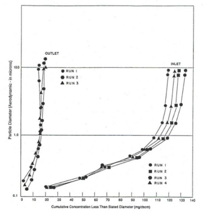
Veneer Dryer Wet ESP Inlet/Outlet Particle Size Distributions
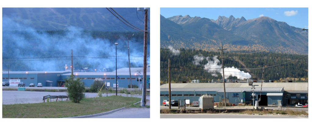
Before and After Installation of Wet ESP on a Veneer Dryer
Biomass Fired Boiler – A second common application for wet ESPs is downstream of a wet scrubber treating emissions from a biomass fired boiler. The data shown in the illustration below demonstrate the effectiveness of the wet ESP system in achieving compliance with the US EPA Boiler MACT regulations as implemented in 2013. The photograph of emissions from a similar biomass fired boiler also shows the effectiveness of this application.
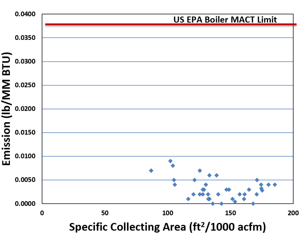
Wet ESP Outlet Concentrations from Biomass Boiler
Fiberglass Forming – Wet ESPs are also used to control emissions from the manufacture of fiberglass. The data shown here clearly demonstrate the ability of a properly designed wet ESP to achieve extremely low outlet particulate concentrations.
| Wet ESP | Gas Flow Rate | Outlet Particulate Concentration | ||
|---|---|---|---|---|
| Unit 1 | 162,000 m³ /hr | 95,310 ft³ /min | 1.7 mg/Nm³ | 0.0007 gr/dscf |
| Unit 2 | 84,000 m³ /hr | 49,429 ft³ /min | n <0.41 mg/Nm³ | <0.0002 gr/dscf |

Unit 1 Wet ESP

Unit 2 Wet ESP
Capital Costs – Generally, wet ESPs are more costly than other emission control technologies, such as wet scrubbers, dry ESPs, and fabric filters. However, beyond that, it is difficult to provide a more specific CAPEX estimate. This is because the capital costs of wet ESP systems vary significantly depending on many factors. Most important is the material of construction. In benign environments with moderate pH and low chloride concentrations, simple 304 or 316 stainless steel is suitable. If chlorides are a problem, higher-grade alloys such as duplex stainless steel or super austenitic stainless may be required. In very aggressive environments, high nickel alloys may be necessary. In addition, site-specific factors can significantly impact the installation cost and overall CAPEX.
In summary, with the advent of the demand for CO2 emission abatement, the cement and lime industry will have to develop the proper control technologies. The leading candidate today is wet scrubbing with amine solutions. These systems will need contaminant-free inlet gas to ensure this technology operates with the lowest operating and maintenance costs. A proven tool for achieving this goal is wet electrostatic precipitation.

