A positive displacement blower with silencers creates the air required for material transport. A feeder assembly is an airlock and allows introduction of material into the high pressure system. The high pressure piping has a thicker wall thickness than low pressure piping. Flatback elbows are used when making a direction change as the high pressure system uses fast velocities to transport material.
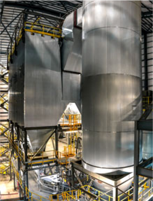
The high pressure system can end at a target box, primary cyclone or primary filter. An airlock is located below the cyclone or filter as to not pressurize the object below the airlock. All air is discharged to atmosphere with a cyclone or filter.

THE BLOWER ASSEMBLY
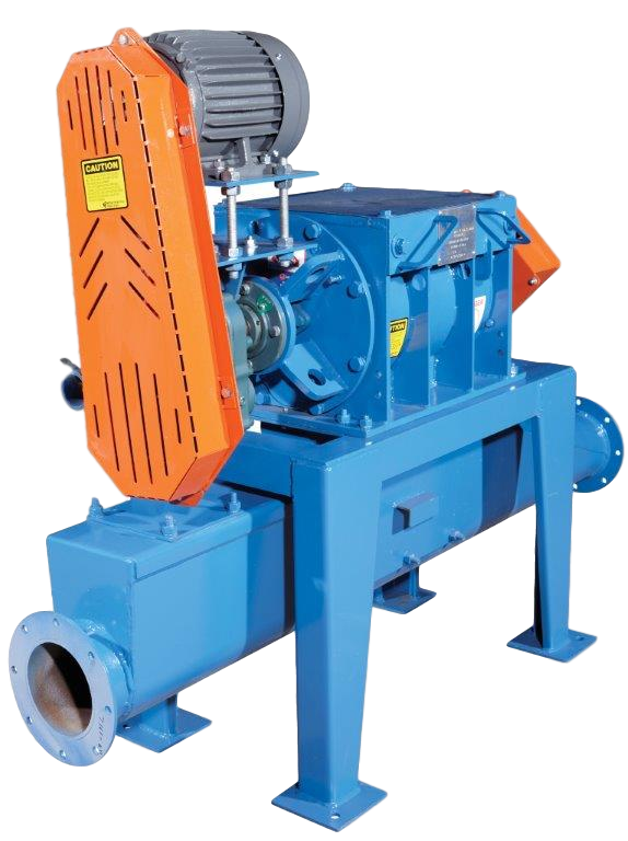
A positive displacement blower is the motive force creating air and pressure required to transport products through a heavy wall pipe. The blower and motor is selected specifically for the design parameters for a system. The blower requires an inlet and discharge silencer to attenuate the gear noise of the blower. The blower is mounted on a base which also includes motor and V-belt drive which powers the blower. After the discharge silencer, a pressure transducer is connected to the piping to sense pressure and provide signals to the plant PLC to protect the blower from an over-pressure event.

After

After
THE FEEDER ASSEMBLY
The feeder is an airlock and is the heart of the feeder assembly, robust in construction, tight tolerances between the rotating rotor assembly and the housing keep air from escaping.
The feeder assembly consists of a rotary airlock, drive, tee-injector and support base. Metered material is directed into the top of the feeder, the feeder internal rotor assembly rotates and allows material to be deposited into the tee-injector below. The feeder size is based on material volume passing through the feeder. The internal helical rotor assembly is constructed of thick steel blades, the ends of the blades have stainless steel overlay tips. The feeder internal housing is machined and chromed to extend the life of the feeder. A chipper quality knife is located at the top on one side and allows for shearing by the helical rotor blades.
A tee-injector is mounted directly below the feeder and allows material to fall from the feeder into an airstream created by the blower assembly. A base supports the feeder and the tee-injector, the centerline of the tee injector is typically 12” off the ground.
THE RECEIVER – HIGH PRESSURE CYCLONE
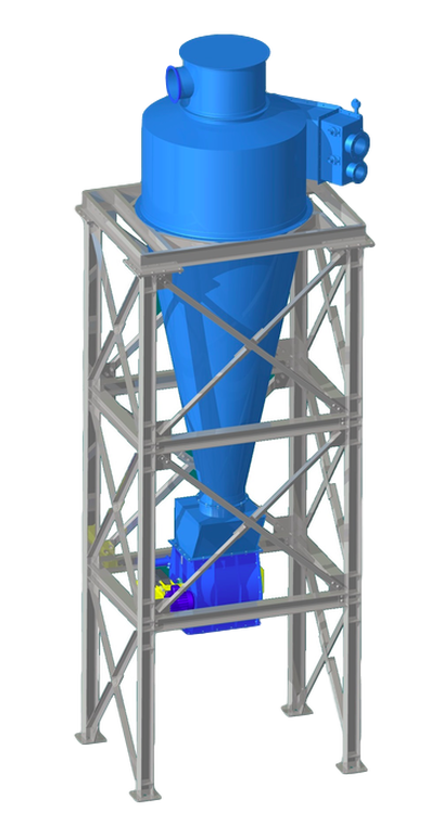
The high pressure cyclone is designed to accept high velocity air and material. An inlet impact liner, body liner and sometimes a cone liner is used to deal with the wear and abrasion caused by high speed materials entering the cyclone. The cyclone employs centrifugal separation, high speed air and dust is pushed to the interior of the cyclone, centrifugal forces separate air and material, material is discharges out the bottom and air discharged out the top. Cyclones are sized specifically for the system air volume, abrasion resistant materials are utilized for longer life of the cyclone


